Installing and connecting the interface
- Wolfgang Granzer
The NETx KNX IP Secure Interface is designed for installation on a DIN rail with a width of 1 unit (18mm). It features the following controls and displays:
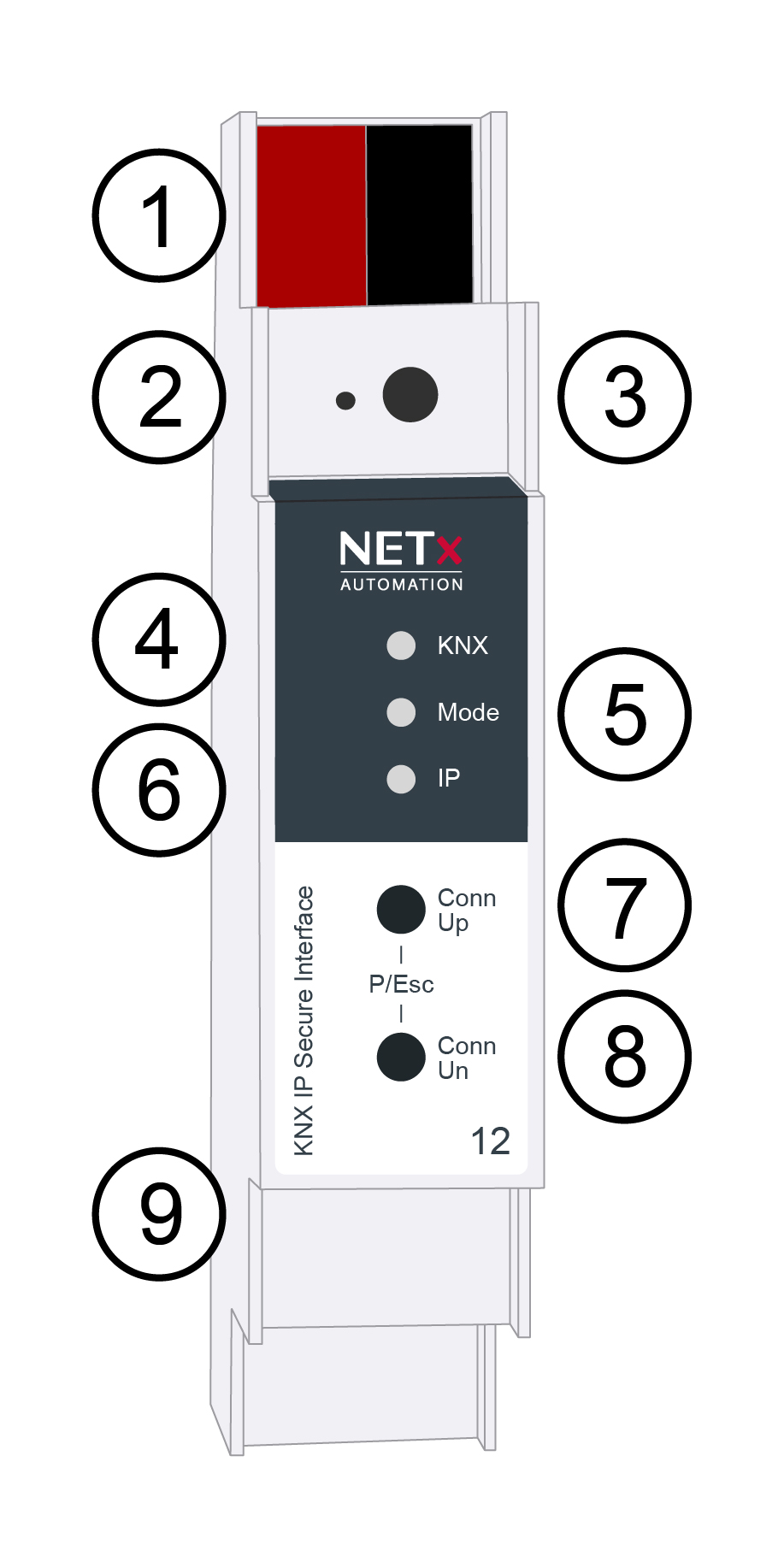
❶: KNX bus connector
❷: KNX programming LED
❸: KNX programming button
❹: KNX LED
❺: Mode LED
❻: IP LED
❼: Conn Up button
❽: Conn Dn button
The NETx KNX IP Secure Interface is powered by the KNX bus. An external power supply is not necessary.
The device is not working without bus power.
KNX programming mode
The KNX programming mode is activated/deactivated either by pressing the flushed KNX programming button ❸ or by simultaneously pressing the buttons ❼ and ❽.
Status display
The KNX LED ❹ lights up green if the device is successfully powered by the KNX bus. This LED indicates telegram traffic on the KNX bus by flickering. Communication failures (e.g. repetitions of telegrams or telegram fragments) are indicated by a short change of the LED color to
red. Overview of the different indications of the KNX LED ❹:
| LED Status | Meaning |
|---|---|
| LED lights green | KNX bus voltage available |
| LED flickers green | Telegram traffic on the KNX bus |
| LED shortly red | Communication failures on the KNX bus |
The IP LED ❻ lights up when an Ethernet link is active. This LED is green if the device has valid IP settings (IP address, Sub net and Gateway). With invalid or nonexistent IP settings the LED is red. This is also the case if e.g. the device has not yet received the IP settings by a DHCP server.
This LED indicates IP telegram traffic by flickering.
Overview of the different indications of the IP LED ❻:
| LED Status | Meaning |
|---|---|
| LED lights green | The device has an active Ethernet link and valid IP settings. |
| LED lights red | The device has an active Ethernet link and invalid IP settings or not yet received the IP settings by a DHCP server. |
| LED flickers green | IP telegram traffic |
The Mode LED ❺ can visualize the status of each KNXnet/IP tunneling connection.
With the buttons Conn Up/Dn ❼ ❽ you can chose each single connection. Conn Up ❼ counts the connection numbers up and Conn Dn ❽ down. The actually selected connection number is indicated by flashing (1x…5x) of the Mode LED ❺. An available KNXnet/IP Tunneling connection is indicated by a green LED and a used tunneling connection is indicated by an orange LED.
Via the Escape function (Esc) this indication can be ended by simultaneously pressing the buttons Conn Up/Dn ❼ ❽.
If neither programming mode nor manual operation are active the Mode LED ❺ can visualize configuration errors.
Overview of the different indications of the Mode LED ❺:
| LED Status | Meaning |
|---|---|
| LED lights green | Device is working in standard operation mode. |
| LED lights red | Programming mode is active |
| LED flashes green 1x ... 5x | Programming mode is not active. Manual operation is active. The selected tunnel (1-5) is not used and free. |
| LED flashes orange 1x … 5x | Programming mode is not active. Manual operation is active. The selected tunnel (1-5) is used |
| LED flashes red | Programming mode is not active. Manual operation is not active. The device is not properly loaded e.g. after an interrupted download. |
Factory default settings
The following configuration is set by factory default:
- Individual device address: 15.15.255
- Number of configured KNXnet/IP tunneling con.: 1
- Individual address of tunneling con.: 15.15.240
- IP address assignment: DHCP
- Initial Key (FDSK) active
- Security Modus not active
Reset to factory device settings
It is possible to reset the device to its factory settings:
- Disconnect the KNX Bus connector ❶ from device
- Press the KNX programming button ❸ and keep it pressed down
- Reconnect the KNX Bus connector ❶ of device
- Keep the KNX programming button ❸ pressed for at least another 6 seconds
- A short flashing of all LEDs (❷❹❺❻) visualizes the successful reset of the device to factory default settings.